Difference between revisions of "Attaching a GPS unit to an LSB"
From University of Washington - Ubicomp Research Page
Karl Koscher (talk | contribs) |
Karl Koscher (talk | contribs) |
||
| (One intermediate revision by the same user not shown) | |||
| Line 1: | Line 1: | ||
| + | This information is specific to the [http://www.usglobalsat.com/item.asp?itemid=125|EM-408 GPS module] we're using, but can be adapted to other GPS modules. <br /><br /> | ||
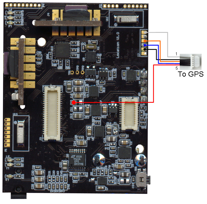
Attach five wires to the LSB as shown. The red wire can be connected to the pad closest to the large connector of either or both of C10 or C11. Cut a GPS cable in half. Splice the wires from the LSB with the GPS wires as shown. | Attach five wires to the LSB as shown. The red wire can be connected to the pad closest to the large connector of either or both of C10 or C11. Cut a GPS cable in half. Splice the wires from the LSB with the GPS wires as shown. | ||
[[Image:LSB-to-GPS.jpg]] | [[Image:LSB-to-GPS.jpg]] | ||
| + | |||
| + | <b>GPS Pinout</b> | ||
| + | {| class="wikitable" style="text-align:center" | ||
| + | ! Pin !! Description | ||
| + | |- | ||
| + | | 1 || Enable | ||
| + | |- | ||
| + | | 2 || GND | ||
| + | |- | ||
| + | | 3 || RX | ||
| + | |- | ||
| + | | 4 || TX | ||
| + | |- | ||
| + | | 5 || VCC | ||
| + | |} | ||
| + | |||
| + | <b>LSB Pinout</b> | ||
| + | {| class="wikitable" style="text-align:center" | ||
| + | ! Pin !! Description | ||
| + | |- | ||
| + | | C10 Pad || VCC | ||
| + | |- | ||
| + | | P2/2 || GND | ||
| + | |- | ||
| + | | P2/3 || RX | ||
| + | |- | ||
| + | | P2/4 || TX | ||
| + | |- | ||
| + | | P2/6 || Enable | ||
| + | |} | ||
Latest revision as of 21:58, 15 August 2007
This information is specific to the GPS module we're using, but can be adapted to other GPS modules.
Attach five wires to the LSB as shown. The red wire can be connected to the pad closest to the large connector of either or both of C10 or C11. Cut a GPS cable in half. Splice the wires from the LSB with the GPS wires as shown.
GPS Pinout
| Pin | Description |
|---|---|
| 1 | Enable |
| 2 | GND |
| 3 | RX |
| 4 | TX |
| 5 | VCC |
LSB Pinout
| Pin | Description |
|---|---|
| C10 Pad | VCC |
| P2/2 | GND |
| P2/3 | RX |
| P2/4 | TX |
| P2/6 | Enable |
