Sensor Board Programming
Contents
Overview
To program the MSB2 sensor boards we will need the following items:
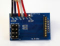
- Blue development board (with JTAG header pins on the far left)
- Atmel AVR JTAG, preferably a USB one
- Atmel AVR JTAG adapter board (with a rainbow colored ribbon cable)
- CSR BlueCore JTAG board (with the adapter board plugged in)
- CSR BlueCore XPSI parallel port cable
- 2.4GHz antenna
- Spectrum analyzer (>2.4GHz)
- A couple USB mini-B cables and the appropriate software/firmware images
- The MSB2 sensor board you want to program
- Required Components
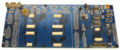
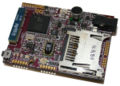
Development Board
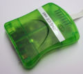
Atmel AVR JTAG
Atmel AVR JTAG Adapter cable
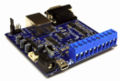
BlueCore JTAG Board
BlueCore JTAG Adapter
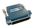
BlueCore XSPI Adapter
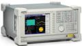
A spectrum analyzer
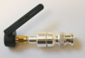
2.4GHz Antenna
MSB2 Sensor Board


The steps are to:
- Plug the MSB2 into the development board
- Program the Atmel firmware
- Program the Bluetooth radio's firmware
- Tune the Bluetooth radio's crystal
Using the Development Board

The blue development board is designed to provide programming, power, USB serial communication, and debugging capabilities for the iMote1, MSB1, iMote2, MSB2 (all revs), LSB, and BT+SD boards. It provides four sets of connectors (on the left) for iMote2 boards and one set of connectors (on the right) for the iMote1 boards. To use the board:
- Plug it in via USB to your computer and install the FTDI USB->Serial drivers (see setting up the FTDI Drivers for help)
- Make sure the jumper (indicated on the right) is removed, only the far right green LED should be lit (indicating USB has power)
- Plug in the board you want to work with
- Then insert the jumper, the green LEDs on the right side should now both be lit
Programming the Atmega128L Firmware
To program the Atmel microprocessor we need to:
- Setup our development board, remove the power jumper
- Attach the Atmel JTAG to our computer
- Download and install the AVR Studio software if you haven't already done so (available here atmel.com)
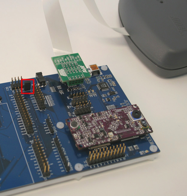
- Plug the Atmel JTAG into our development board (see the picture above for the proper orientation of the connector)
- The flex cable attached to the JTAG's adapter board can sometimes come loose, make sure that it is propperly seated before attempting to program
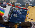
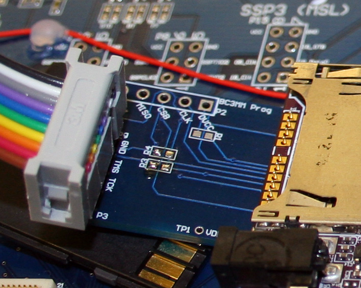
- If programming an MSB, take the Atmel JTAG adapter and make sure that the ribbon cable is plugged in the picture below. Then plug the rainbow colored ribbon cable into the development board, making sure it matches the orientation shown below.
-
- If programming an MSB, next, making sure the power jumper is removed and the sensor board is off, we take the adapter board and our sensor board and insert the adapter board into the holes underneath the miniSD card slot on the sensor board.
- The adapter pins are very delicate so be careful when handling them so they don't bend. If they do bend do not use your fingers to realign them as the pins will break off easily, use a tool and very slowly bend them back into alignment
- With the adapter board plugged into the sensor board we need to plug them into the development board, once the board is plugged into the development board we need to make sure the adapter's pins have good contact with the plated holes on the sensor board. We do this by pushing a SD card underneath the adapter board and the unused headers on the development board, there only need to be enough pressure to ensure that the pins are touching the plated holes edges -- be careful to not bend the pins or to force the sensor board out of its slot
- If programming an LSB, plug in the LSB to the development board through a couple of advanced breakout boards (needed to elevate the LSB so that the sensor daughterboards don't hit the development board).
-
- Now that our hardware is setup, double check that everything is setup properly and inser the power jumper into the development board
- Next start the AVRStudio software. If you have a project for the sensor board already setup select it. Otherwise we need to create a new project for the sensor board. To do this click the Create New Project button, select a project name and output directory hit next, then select the debug platform JTAG ICE and device ATmega128 then hit finish.
-
- With AVR Studio setup we can now program the sensor. To access the program menu click the icon with a microchip with AVR written in it. You can also use Tools->Program AVR->Connect. You should be presented with a menu prompting you for a flash and EEPROM file. Typically you will only need to select a hex file and hit program.
- However, the first time a board is programmed you will need to set the fuse settings. To do this select the fuse tab, and make sure the check marks match the pictures below. Note: You should never program the lock bits or forget to leave the JTAG programming interface selected. Failing to do so will turn your sensor board into a nice paper weight, until the microprocessor can be removed and replace (with is time consuming and very expensive).
- Note: It takes AVR Studio a few seconds to read out the fuse settings, before these settings are read into the menu the default selection of checkboxes are set to disable JTAG programming. If you hit program before the fuse settings are read you will immediately disable JTAG programming and will be locked out of the chip! This is quite time consuming and costly to repair so exercise extreme caution when programming these fuses.
-
- If you encounter any errors getting your board to program or connecting to the AVR JTAG be sure to check your connections and try again. If it still fails reconnect the board, turn the AVR JTAG on/off and restart AVR Studio.
- Once the firmware has been programmed the sensor board is ready to be used, the only thing left is to setup the Bluetooth radio


Programming Errors
- If you encounter any errors while programming be sure to check the following:
- Check that the sensor board is properly plugged into the development board by carefully pushing down on it till the connectors are fully mated. If the connectors will not mate properly make sure nothing is stuck inside the connectors that might block them from mating and that you have the proper orientation. If you do find something inside the connector use a small plastic tool to carefully remove it, the connector housing and pins can be easily damaged and are difficult to repair!
- Make sure that the JTAG adapter board is properly attached to the debug board and double check that the flex cable is inserted correctly in the adapter
- If you have anything connected to the pins like oscilloscopes, daughter boards, etc. disconnect them as they may be interfering with the JTAG programming
- Make sure that no stray wires are accidentally shorting the pins on the board
- Check that the serial/USB cable is fully connected to the JTAG and that there are no lose connections
- You can reset the sensor board by removing the board and replacing it
- You can also reset the JTAG by removing the power cable or flipping the power switch. Sometimes the JTAG and the computer will become out of sync causing connection problems
- If you are still unable to program verify that you have can talk to the device at all by switching to the Fuse menu. AVR Studio should read the current fuse settings when you switch to this menu if it is able to read these settings the JTAG connection should be fine. If not double check the above suggestions until you get a reliable connection
Programming the BlueCore3 Firmware
To program the BlueCore firmware we'll use the BlueCore JTAG, XSPI Parallel port cable, and a BlueCore adapter board.
- The CSR BlueCore firmware images are not available for download, please contact Jonathan if you need access to the firmware or PSR files
- You will need to install the BlueSuite software, as this software is not free you cannot download it
- BlueSuite will install a parallel port driver, so you will need to reboot your computer.
- Note you will need a parallel port that is in ECP mode, this may require changing your BIOS settings. If you do change your BIOS note you must turn your machine off and wait about 30 seconds before reboot for the changes to take effect
- Plug the XSPI parallel port cable into your parallel port and plug it into the JTAG board
- Plug a mini-usb cable into the JTAG board (note do not connect these devices to multiple computers -- parallel port into a desktop USB into a laptop -- as this can have unpredictable effects)
- Next we need to plug our adapter board into the programming header on the sensor board, like we did above with the Atmel programming. Again we will need to place a SD card underneath the adapter to ensure that the adapter's pins make good electrical contact with the sensor board's programming header.
- For this part of our programming we don't need the serial connection to the development board. Sometimes this connection can cause problems, if it does unplug the serial jumper cable nearest to the sensor board and leave the other end plugged in. You can remove it completely; however, you will need to match the correct colors when you need the serial connection.
- Next we start the BlueFlash software
- Hit the Stop Processor button, at which point you should get some text in the upper right corner identifying the type of flash found on the device. If you have problems check your connections and that your parallel port is setup correctly.
- The BlueCore JTAG board has several LEDs on it that should flash when you press this button the one nearest the USB connector shows activity from the computer to the chip (MOSI) and the next one over shows activity from the chip to the computer (MISO)
- First we load the bootloader onto the BlueCore chip, this should be a file named 'loader_unsigned.xpv'. This generally takes about 30 seconds.
- Next, we load the Bluetooth stack onto the chip, this should be a file named 'stack_unsigned.xpv'. This usually takes a minute or two.
-
- Once we're done flashing the firmware we will need to set the Persistent Store keys, which are basically EEPROM settings for the processor. To do this we start PSTool
- Next select that we want to connect via SPI BCCMD on the LPT1 and hit ok
- If the SPI connection is successful we should get a window displaying the PS keys, rather than set each key individually we will set them all from a file, we do this by selecting File->Merge and select our "FinalPSRs.psr" file
- This will take several minutes to finish programming during which time the PSTool window may appear to freeze
-
- Next we need to set the Bluetooth radio's MAC hexadecimal address, this number is of the form: 00:02:5b:00:XX:YY To set the Bluetooth address scroll the window to "Bluetooth Address" and change the last 4 hexadecimal numbers to match those printed on the sensor board.
- The Bluetooth address on the sensor boards is of the form: 00:02:5b:00:XX:YY where
- XX is the run/family of sensor boards (each time boards were assembled a new run number was used)
- YY is a decimal counter/serial number ID of the boards
- Note, even though the Bluetooth MAC address is a hexadecimal number we don't count board serial numbers in hex. So there should never be a board where the last 2 digits have A,B,C,D,E, or F in it, this means there are maximum of 00-99 serial numbers per run number.
-
- The Bluetooth address on the sensor boards is of the form: 00:02:5b:00:XX:YY where
- At this point the Bluetooth firmware is all setup. The only remaining step is to tune the Bluetooth radio


Connecting the BlueCore3 to the Serial Port

The BlueCore chip connects via the BTUART on its iMote2 connectors, to connect this UART to the primary serial port of the development board we need to connect a set of jumpers like thos shown in the figure on the right. The mapping is:
| BTUART (P14) | Primary Serial Port (P25) |
|---|---|
| BTRxD | TxD |
| BTTxD | RxD |
| BTCTS | RTS |
| BTRTS | CTS |
Programming the BlueCore via the boot loader
-
The BlueCore is capable of being programmed over the serial line using the H4 uart protocol. There is currently no linux implementation that we can use to update the firmware (although documentation exists to create one), instead we can use the Windows DFU wizard to do the serial programming for us. As this takes considerably longer than programming via SPI it is not recommended.
Tuning the Bluetooth Radio
Each BlueCore3 baseband is self calibrated according to the ambient/chip temperature and the input clock. Since the chip takes care of tuning the temperature we just need to set the appropriate tweaking for the crystal, this is set by:
- the BlueCore radio broadcast an RF signal at what it believes 2.441GHz
- a spectrum analyzer set to 2.441GHz scanning the RF spectrum for this signal
- a crystal trim value that adjusts the BlueCore's signal until it outputs a true 2.441Ghz signal
Note that if the PS keys are ‘merged’ this may wipe out our tuned crystal setting, so this step may need to be repeated if the PS keys of a BlueCore are ever reset
The basic process is:
- Program the firmware and persistent store keys on the Bluetooth radio
- Determine the crystal trim value (in hexadecimal) using a spectrum analyzer
- Convert the hexadecimal number to decimal
- Program the converted value into the persistent store keys
Setting up the Spectrum Analyzer
- With the spectrum analyzer off, plug in the 2.4GHz antenna.
- This should require no force and doesn’t have to be very tight, be careful to not bend or break any of the delicate leads
- Turn on the spectrum analyzer it will boot into Windows XP and after a few moments will start the spectrum analyzer software.
- It is generally a good idea to leave the system running for about 15minutes before you use it so the device has a chance to warm up and calibrate itself.
- First we set the center frequency, by hitting button 3
- Enter "2.441" on the keypad
- Hit the "GHz" button to indicate that its 2.441GHz
- Next we set the span (how wide the visible spectrum is) by hitting button 6
- Then we enter "400" on the keyboard
- And hit the "kHz" button to indicate a span of 400kHz, in general all the Bluetooth radios should transmit within this span but you can set it lower or higher if needed
- Once the radio is transmitting there should be a single peak like the one shown in the figure. By default the purple cursor (seen as a small box on the right side of the peak in the picture) will point to our desired center frequency of 2.441GHz. If you want you can hit the "peak" button to have the cursor highlight what frequency the highest peak is at. In general its better to leave the cursor at 2.441GHz so you don't end up using the wrong center frequency by mistake. You can reset the cursor by entering 2.441GHz in the keypad.

Any 2.4GHz spectrum analyzer will work the only requirement is it being somewhat calibrated and having an appropriate 2.4GHz antenna. The instructions below are for using a Tekntronix RSA3408A 8GHz digital spectrum analyzer. Here are the steps to setup the spectrum analyzer so you can tune the radio:
Using BlueTest to get the crystal trim value
-
To get the radio to emit a 2.441GHz carrier wave for the spectrum analyzer we need to use the BlueTest3 software to access the Bluetooth radio's RF test modes. We do this with the BlueTest3 program (BlueTest3.exe) which can communicate with the BlueCore chip via the serial port of the SPI interface. To setup the RF test mode and find the right crystal trim values we need to do the following:
- Start the software and select the H4 transport, the appropriate serial port (this will be the COM number of the first USB Serial port installed by the development board), and the 921,600 baud rate.
- Once you hit ok the software will attempt to communicate with the BlueCore chip, if it fails the software may exit or display an error message. If this happens be sure to check all your connections and ensure that the chip is powered and fully seated in the development board. If the software is able to communicate with the BlueCore chip than the firmware version will be displayed in the bottom console (something similar to 'BC3 (Hardware ID 43) firmware version 4290.'
- Once the BlueTest software is up and running we'll first send a command to the BlueCore to have it transmit a carrier wave at 2.441GHz, scroll the "RF Test Modes" box to the "TXSTART" entry and select 'Execute'. At this point a peak should appear on the spectrum analyzer assuming its setup correctly.
- With the carrier wave being transmitted we can now tune our crystals settings, to do this we scroll the "RF Test Modes" box to the "CFG XTAL FTRIM" entry and hit execute. So long as we don't do anything else the BlueCore should continue to transmit its 2.441GHz signal so we don't have to set the crystal trim and then execute the TXSTART, it should always be transmitting. Now, we can tune our crystal trim value until the spectrum analyzer shows the peak centered at 2.441GHz. The trim value used here is in hexadecimal so be sure to use the appropriate number when stepping the trim value up and down. After finding the number, write it down and we will have to program the value into the BlueCore using the PSTool.


Hexadecimal to Decimal Table
-
The CFG XTAL FTRIM value is set in hexadecimal, however, the "Crystal Frequency Trim" value is set in decimal. Here's a quick look up table for mapping from hexadecimal to decimal:
| Hexadecimal | Decimal | Hexadecimal | Decimal | Hexadecimal | Decimal |
|---|---|---|---|---|---|
| 0x10 | 16 | 0x20 | 32 | 0x30 | 48 |
| 0x11 | 17 | 0x21 | 33 | 0x31 | 49 |
| 0x12 | 18 | 0x22 | 34 | 0x32 | 50 |
| 0x13 | 19 | 0x23 | 35 | 0x33 | 51 |
| 0x14 | 20 | 0x24 | 36 | 0x34 | 52 |
| 0x15 | 21 | 0x25 | 37 | 0x35 | 53 |
| 0x16 | 22 | 0x26 | 38 | 0x36 | 54 |
| 0x17 | 23 | 0x27 | 39 | 0x37 | 55 |
| 0x18 | 24 | 0x28 | 40 | 0x38 | 56 |
| 0x19 | 25 | 0x29 | 41 | 0x39 | 57 |
| 0x1A | 26 | 0x2A | 42 | 0x3A | 58 |
| 0x1B | 27 | 0x2B | 43 | 0x3B | 59 |
| 0x1C | 28 | 0x2C | 44 | 0x3C | 60 |
| 0x1D | 29 | 0x2D | 45 | 0x3D | 61 |
| 0x1E | 30 | 0x2E | 46 | 0x3E | 62 |
| 0x1F | 31 | 0x2F | 47 | 0x3F | 63 |
Setting the Crystal Trim in the Persistent Store Keys
-
Once we've figured out the appropriate crystal frequency trim value, we need to set this value in the chips on-board flash so it uses it each time it boots. To do this we use the PSTool program, which we can access via the serial port:
- Even though the interface is slightly different we choose the same settings for the PSTool that we did for the BlueTest software, H4 Transport, the first serial port installed by our USB driver, and 921,600 baud.
- Scroll to the "Crystal frequency trim" setting (or use the filter) and set the decimal value of the hexadecimal number found using BlueTest. You can use the above table to make the conversion quicker
